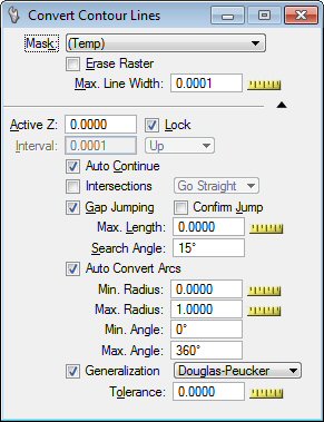
Convert Contour Lines tool settings
| Setting | Description |
|---|---|
| Erase Raster |
If on, the raster in the selected extent will be erased. |
| Max. Line Width |
Used to determine the maximum width of raster lines. All lines, or parts of lines, or any raster object wider than this value will not be considered as a raster line. This value is given in pixels. Use the Measure tool to measure the width of the larger lines you want to convert. |
| Active Z |
When the first contour line of a series is converted, it is given the Active Z that you specified in the Active Z text box in the Tools Settings window. The second one is given an active Z incremented with the Interval value. The increment will be positive if Up is selected, negative if Down is chosen. |
| Interval |
The second contour line of a series is given an active Z incremented with the Interval value. The increment will be positive if Up is selected, negative if Down is chosen. |
| Lock |
If all contour lines to be converted happen to be at the same elevation, set the Active Z and lock it. Then, the Interval and the Up/Down options are not used. |
| Auto Continue |
If on, the Continue Element tool will be automatically selected after a part of a contour line is converted. That allows continuation of converting this contour line from one end, and then from the other end. Use the Reset button to switch from one end to the other. After both ends have been continued, press Reset to return to the Convert Contour Lines tool. If the whole loop of a contour line is converted and a closed shape results, this mechanism does not apply. |
| Gap Jumping |
Use to set the Maximum Gap Length and the Searching Angle. Use the MicroStation Measure Distance tool to estimate the gap length. Line breaks will automatically be bridged according to the settings you specified. If a line is located within the specified distance and angle, the gap jumping procedure will continue. If no line is found, the procedure is stopped. |
| Confirm Jump |
When this option is ON, the vectorize engine stops after it performs a jump and waits for user input to continue. |
| Auto Convert Arcs |
If on, this feature tries to recognize arcs along the line strings generated with the convert function. |
| Generalization |
If on, when a vector line is generated by automatic line conversion, it is passed through a generalization process. This process removes points from the original result to keep only those considered as necessary to characterize the original pathway of the vector line. The following options are available:
|
| Tolerance |
Use to enter the tolerance factor:
|